Name of Experiment: Full Wave Rectification (using bridge rectifier)
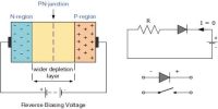
Theory: Rectification is a process by which alternating voltage is converted into a direct voltage. Semiconducting diode performs this work effectively. There are two types of rectifiers, viz.- half wave rectifier and full wave rectifier. A full wave rectifier is discussed below.
Bridge Rectification is the process by which alternating current (a.c.) is converted into direct current (d.c.) is called rectification and the circuit which is used in this work is called a rectifier. Rectifiers are mainly classified into three types: Half-wave rectifier, Center tapped full-wave rectifier and Bridge Rectifier. All these three rectifiers have a common aim that is to convert Alternating Current (AC) into Direct Current (DC).
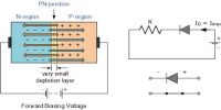
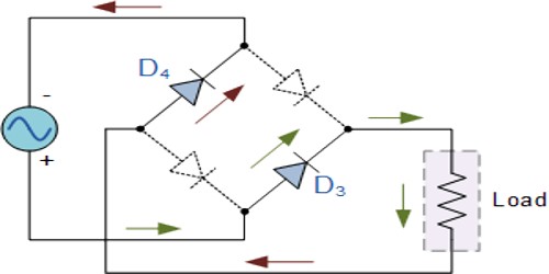
In full wave rectification for both half of the input a. c. voltage current flows through the load resistance in one direction. For one half of the input voltage pair of diodes becomes forwardly biased, when the other pair of diodes remains in reverse biased. Again for the second half of a. c. input voltage the first two diodes become reverse biased and the second two diodes become forward biased. So the current flows through the load in one direction. In this way, in both halves of the a. c. input voltage across the load is produced in one direction. This d. c. output is not smooth d. c. but pulsating d. c. i.e., both a. c. and d. c. components are present in the output. In order to get pure d. c. voltage the output is smoothed by a filter circuit.
Apparatus:
- Step down transformer,
- Bridge rectifier,
- Capacitor (330 μF or 50 μF),
- Resistor,
- Multimeter,
- Oscilloscope,
- Connecting wires etc.
Circuit connection: According to the figure below the electric circuit connection is made.
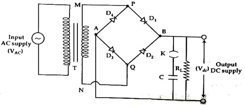
The primary coil of the transformer is connected with the a. c. supply. The two terminals of the secondary coil are connected with opposite terminals PQ of the bridge rectifier. The other two terminals of the bridge rectifier are connected to the capacitor and load resistance RL.
Working procedure:
- According to the figure above the circuit, a connection is made. During a positive half cycle of the secondary voltage M terminal of the transformer becomes positively charged and N terminal becomes negatively charged. In this situation, diodes D1 and D3 become forward biased and diodes D2 and D4 become reverse biased. So, along MPD1BAD3QN current flows and across RL potential drops. Again during negative half cycle terminal M becomes negatively charged. So, along NQD2BAD4PM path current flows will be seen that current through load RL flows always in the same direction.
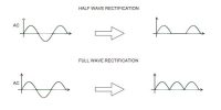
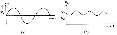
- Wave shapes of the input and output are observed through the oscilloscope. Input and output will be observed as in figures (a) and (b).
- The voltage across RL is measured by the help of oscilloscope.
- If an oscilloscope is not available, a. c/d. c voltage can be measured by a voltmeter.
Precautions and Discussion:
- Connections of the diode should be correct.
- Terminals of the wires should be made tight.
- Instead of oscilloscope a. c/d. c voltmeter may be used.
- Step down transformer is to be used.