Experiment: To determine the unknown resistance by a Post Office Box
Theory: By inserting appropriate resistance in the post office box current passing through the galvanometer can be made zero. If the potentials between points B and D are equal i.e., there is no potential difference between the two terminals of a galvanometer, then this phenomenon happens. In this situation, no deflection is found in the galvanometer and the bridge remains in the equilibrium condition. Now according to Wheatstone bridge balanced condition,
P/Q = R/S
S = R x Q/P
If P = 10 ohm and Q = 10 ohm
So, S = (10 x R) / 10 = R ohm
Again by putting P = 100 ohms and Q = 10 ohms, if the experiment is performed then it will be seen,
100/10 = R/S
So, S = 10R/100 = 1/10 R ohm.
Similarly taking P = 1000 ohm and Q = 10 ohms, if the experiment is performed, then we get 1000/10 = R/S
So, S = 1/100 x R ohm … … … (1)
By this instrument, the value of unknown resistance can be determined up to the second digit after the decimal. Here R = resistance of the 3rd arm.
Description of the instrument
A Post Office Box can also be used to measure an unknown resistance. It is a Wheatstone bridge with three arms; while the fourth arm(s) is the unknown resistance. Post office box (in short, PO box) is the special form of Wheatstone bridge. It is called a post office box because it was originally used by the postal department for the measurement of the resistance of the telegraph wires and cables.
Normally, with the help of this instrument, we can measure both low and high resistances. It is composed of some fixed value resistance coils. Coils are arranged in succession and form three arms of the Wheatstone bridge. The experimental unknown resistance S is the fourth arm of the bridge. Like the resistance box, here also coils are in a box. On the top platform of the box, two ends of each coil are connected by solid brass blocks. Brass blocks an arranged in adjacent three rows. Between two successive blocks, there is an arrow-shaped gap. If the plug of the gap is withdrawn fixed resistance is included in the circuit.

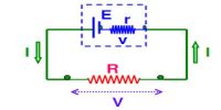
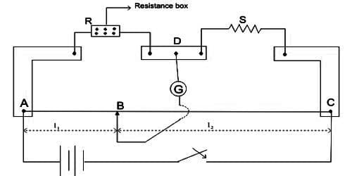
In Figure, the schematic diagram of the post office box is shown. In this instrument, three sections of coil resistances of varying magnitudes are connected by plugs and are marked as AC. CD and AE which constitute respectively the three arms P, Q, and R of the Wheatstone bridge. The arms P and Q are called ratio arms. Each of if contains three resistors of 10, 100 and 1000 Ω values connected in series. Third arm R normally consists of resistances from 1 Ω to 5000 Ω connected in series. When the plug of any coil is taken out, its resistance will be included in the circuit. An unknown resistance S is connected between points D and E which forms the fourth arm of the Wheatstone bridge. A battery B is connected between points A and D through a tapping key K1 and a galvanometer is connected between points C and E through another tapping key K2.
The lower portion of the key K1 and the point A is connected internally. Similarly, point C and the lower portion of the key K2 is connected internally. So, try the key current in the main point and by the key K2 current in the galvanometer can be made on and off.
Procedure:
(1) By rubbing the ends of connecting wires and contact points thoroughly connection is made tightly according to the figure.
(ii) From each arm of P and Q, 10-ohm resistance plugs are taken out. Keeping the resistance of the third arm R zero, first the key of the battery circuit K1 is pressed and then the key K2 of the galvanometer circuit is pressed and the deflection of the galvanometer is observed. Now withdrawing the ∞ (infinity) plug the deflection of the galvanometer is observed again. In this case, if the deflection of the galvanometer is opposite to the first deflection, then it is considered that the circuit connection is alright.
(iii) Starting from the higher values of resistance of the third arm deflections of the galvanometer are noticed by reducing the value of resistance progressively. When the galvanometer gives zero deflection for P = Q = 10 ohms, the unknown resistance S = R will be equal to the third arm resistance. If the deflection is not made zero, then due to the two successive resistances the deflection will be opposite. In this situation, the value of the unknown resistance S is between these values.
(iv) Now in arm P instead of 10 ohms, 100-ohm resistances are inserted. As before the resistance of the second arm, Q is kept at 10 ohms. So Q/P ratio will be 1/10, hence in balanced condition R = 10 S. Now as before resistance plugs from the third arm R are withdrawn so that galvanometer deflection becomes zero. In this situation, unknown resistance S = R/10.
(v) Similarly, 1000 ohm resistance is inserted in arm P and in Q arm 10-ohm resistance is inserted and the experiment is performed as before.