A changing current not only induces an emf in a nearby circuit, it also induces an emf in the source circuit. As an example, we consider a variable voltage source V(t) connected to a solenoid wound around a cylindrical rod made of a material with permeability μ as in below Figure (a).
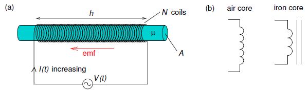
Figure: (a) Solenoid connected to a variable voltage source; arrow shows direction of the back-emf induced due to an increasing current. (b)—Circuit symbols for an inductor.
The magnetic flux through the solenoid is proportional to the current ϕB = LI where L is the self-inductance (or simply inductance) of the loop which depends only on its geometry. In the case of the solenoid shown, with current I(t), the magnitude of magnetic field inside the solenoid is approximately
B (t) = μ (N / h) I (t)
and so the magnetic flux threading the N coils of the solenoid is
ϕB (t) = N Aμ (N / h) I (t)
Giving,
L = μ (N2 A / h)
If the current changes, the emf around the loop is
Ɛ = – (d ϕB / dt) = – L (dI / dt)
Thus, changing the current through a circuit induces a “back emf” which tends to oppose the change in magnetic flux (Lenz’ law) as shown in Figure (a). Circuit elements designed to have significant self-inductance are called inductors and would usually have a core made of a magnetically soft material, e.g. soft iron and, as with transformers, the core would often be in the shape of a torus to minimize magnetic flux leakage. Circuit symbols are shown in Figure (b).